This week was oriented to electronics production. PCBs are a way of simplifying circuits that in another case would be a maze of cables on a breadboard, it also avoids the chances of errors and short circuits. We learned how PCBs are built. For me was especially interesting to know that we can build PCB circuits with a coper vinyl since my intention for the final project is to develop a series of wearables that would need some electronics application. Eventually, the use of this type of PCBs can be risky since there are more chances for the coper to over-bend.
There are 2 types of PCBs: one side and two sides PCBs. On one side PCB, the different layers are made of soldier mask, coper and a substrate. Only allowing us to sell different components on one side. If we have the chance of using a CNC, standoff milling is a great option for this type of PCB. Two sides PCBs, as its name indicates, allow us to sold components on both sides of the board. Made of solder mask, coper, substrate and another layer of copper followed by another soldier mask. There are different PCB compositions from FR1 to FR6. The most used substrates are FR1(Phenolic resin/Kraft paper) and FR4 (Epoxy resin/Glass fabric), being the latest the most chosen among designers. Nevertheless, at FABLAB Bcn we use FR1 since the quality and price are good enough for most of the project's purposes. There is also a multilayer type of PCB which contains multiple layers of PCB sandwiched together. It’s very important to use specialised glue.
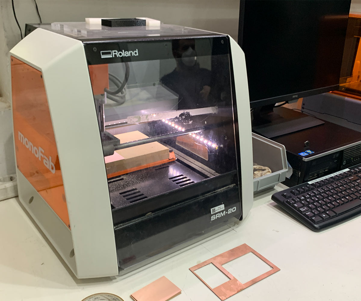
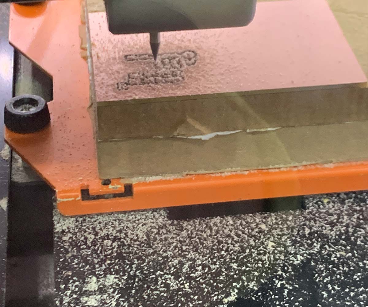
Etching vs Milling. The etching fabrication process uses a lot of chemicals and it's quite hard to control the process but reduces the amount of waste. While milling needs an accessory and produces more material waste but the result is high quality. For milling is important to always use flat en mills to cut all the material evenly. 1/64’’ to draw the path. 1/32’’ to cut the PCB off. Tool path: 2-4 ø offset. Very important to only cut the copper and not the substrate. To prepare the files for the milling machine we’ll use modsproject.org The files should always be in a PNG or SVG format, black and white. 2 files, one for the traces and one for the drill. The resolution 1000 PPP. Mill raster 20. The offset number is the times the milling goes, set on 4. Speed: 3mm/s for trace , 1.5 mm/s for cutting. Was very interesting to see how the machine actually works and bringing all the theory to the ground was more than necessary.
Weekly task
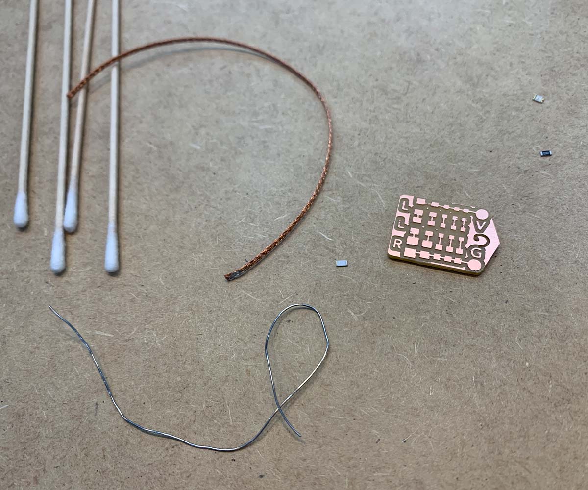
Finish (by pairs) your LED BADGE soldering the SMD components and test it(make the led light up with the power supply.
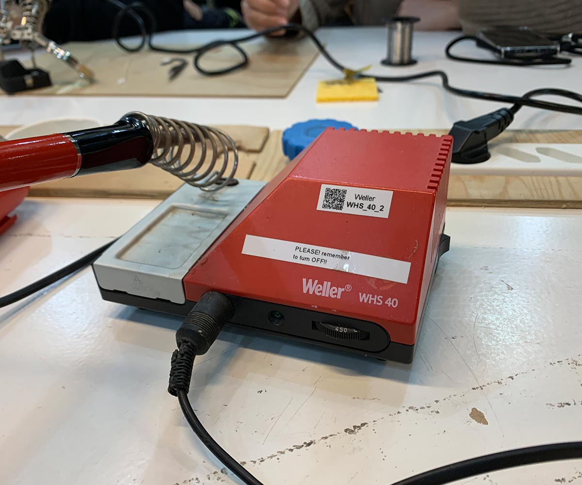
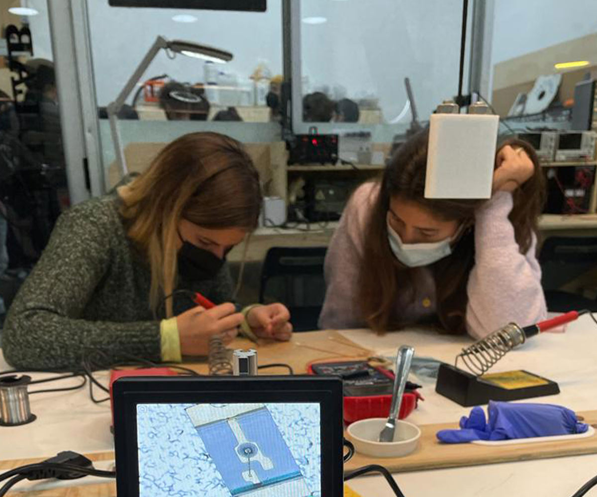
The hands-on moment was a bit scary for me. We were asked to weld some components on an already cut PCB. I found the procurement tremendously complex for the accuracy needed since I feel that I cannot be so precise on such a small scale. Marina and I did the task during class but we forgot to take a picture of the end PCB. We successfully weld resistors and LED lights checking with the multimeter and the light went on.